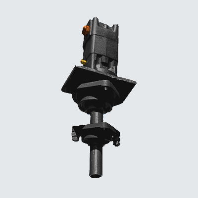
The Universal Rotor is a tractor-mounted or stand-alone rotor that can be fitted with a wide array of toolheads – everything from a wheel, sawmill, cement mixer, pelletizer, to a hammermill, string trimmer, posthole digger, tree planting auger, slurry mixer, and many others. Shafts, motors, and toolheads are replaceable and scalable.
The Universal Rotor Construction Set (URCS) is linked to the LifeTrac construction set – it includes not only the flexible wheel units but various implements. The URCS focuses on scale/power/speed variations of the Rotor, and the different implements that can be mounted – from wheels to cutting blades.
Direct applications of the universal involve mounting the universal rotor to a structure, and adding an ‘implement’ onto the rotor. In the tractor wheel, the mounting is the tractor frame, and the ‘implement’ is a pneumatic wheel or steel wheel. The universal rotor can also be attached to the tractor loader, or to any stationary structure – and is designed to fit on two 4×4” tubes spaced 4 inches apart.
Universal rotor power/speed can be scaled by mounting different hydraulic motors to the UR, or electric motors can be used. A simplified universal rotor may be used in the hydraulic microcar, where the wheels are coupled directly to the motor shafts – such as in Yann Lischetti’s OSE-Wikispeed hydraulic hybrid from 2013.
A rotary encoder may be added to the universal rotor to create applications towards an industrial robot, an indexing head, or a CNC precision machine. Coupled with hydraulic solenoids, GPS, geolocation, or computer vision, applications include autonomous vehicles and automated precision agriculture.
The Pelletizer, Chipper/Hammermill, Dimensional Sawmill, Well-Drilling Rig, 50 kW Wind Turbine, Microcombine Thresher, and Bioplastic Extruder are direct applications of the universal rotor, and combined with precision machining structures, the Universal Rotor also include the heavy duty CNC Multimachine with lathe, drill press, slow cutoff saw, surface grinder, and other machines of fabrication.
The Pelletizer is a roller die and disk where the disk spins, and the small gap between the roller and disk die is adjustable based on the feedstock being pelletized. The UR must be attached to a frame of some sort. The Pelletizer includes a mechanism for ejecting the pellets from the Pelletizer chamber once the biomass is pressed through the disk die. Thus is accomplished by a rotating conical disk under the disk die, which spins with the disk die as it is attached to the same shaft. There is a disk-roller spacing speed adjustment mechanism. A hopper is used to feed the biomass feedstock from the top.
The Rototiller/Soil Pulverizer is the universal rotor attached to a universal mount frame of 4×4″ tubing. A shaft may be coupled via a splined coupler with shear pin. Tines are mounted on a square shaft or a round shaft if bolt holes are drilled through the shaft. The times should be replaceable by sliding onto the shaft, if the bearings and coupler are dismounted. To allow for easy dismounting, the bearings are larger than the shaft, and a bushing is used to make the shaft fit in the bearings. Once the bearing is moved past the bushing, the shaft can be slid through the larger bearing very easily. Adaptation to different rototiller functions is desirable here, for easy lifetime maintenance of tines, which are the wearable parts.
The Cement Mixer is a rotating drum with a batch loader. The capacity should be 2/3 of a cubic yard per 5 minutes of mixing, or 8 cubic yards per hour. A good configuration is a loader-mounted mixer, such that the cement is delivered to the required place with the tractor.
A soil mixer is a tractor-mounted device that uses a rotor to mix cement and soil together for pressing stabilized earth blocks. It consists of a soil Pulverizer shaft that rotates inside an enclosure and allows the soil to be mixed violently, with a bag of cement broken over the soil mixer prior to closing the soil mixer.
A Chipper/Hammermill is a rotor inside an enclosure with loosely-attached knives for the cutting action. Material is fed in a way that shards move away from the feed aperture. A screen allows broken biomass to fall through while keeping larger pieces in the milling chamber until they sufficiently small to fall through the screen. A fan below the screen removes the milled material through a chute that can be oriented in an appropriate direction to allow collection of the hammer-milled matter.
The Dimensional Sawmill is an application of 2 universal rotors mounted at right angles to one another to allow the production of dimensional lumber with one pass. The last prototype of the sawmill involved a trailer mounted machine, but the next iteration is intended to be a front-loader mounted device where height is set by 2 hydraulic cylinders with linear encoders that move the cutting head up and down. The log moves on the y axis (transverse axis) which rests on the ground, and is about 8′ long, while the longitudinal x axis is 20′ long. The tractor deposits the log carriage on the ground and is subsequently used to move the logs – allowing full tractor power to be used either for log moving or powering the sawmill. This configuration allows a short log carriage to be used while simplifying y motion by separating the x motion from y motion.
